Pages

Wednesday 2 December 2015

Arnold aiMotionVector with transparency

I will show one method of rendering motion vectors for an object which has transparency.

Here is the scenario:

I have some snowflakes which are comprised of simple polygon meshes instanced to some particles.
I have a circular ramp with noise to give the snowflakes a feathered edge.


What I want to achieve is to render the beauty in one pass and then a motion vectors pass. The motion vectors must have the same opacity as in the the beauty pass.

Here is the trick: In the ramp which controls the opacity, replace the white colour with an aiMotionVector node.

Set the output to Raw in the aiMotionVector node.


Here is the shader network.


Apply this shader to the snowflakes in a seperate render layer. This will be the motion vector pass


For the motion vector pass, enable Motion Blur in Arnold's render settings.


This will give each snowflake an RGB value.


However there is a problem. We do not want the snowflakes to be motion blurred, we just want them to show the motion vectors.

To stop each slowflake being rendered with motion blur, click the Ignore Motion Blur option in the Override tab of the Arnold render settings


That will give snowflakes with opacity and motion vector information in RGB


One more problem remains - the position of the particle at the time when motion blur is calculated is not the same as the position of the snowflake when the beauty pass is rendered. To fix this, select Start on Frame in the Motion Blur options in the Arnold render settings.


Now, into Nuke.

Load the rendered beauty pass and the motion vector pass. Each snowflake should overlap perfectly (if not, check the Start on Frame option)


Combine the two renders by using a Shuffle Copy node.
Shuffle R -> u
shuffle G -> v


Now use a VectorBlur node to produce the motion blur effect


Thursday 19 November 2015

High Resolution Cloth Simulations

Here I will describe the method I have been using to create high resolution cloth simulations, based upon low resolution pre-vis cloth. This method is derived from the work of David Knight - thanks David!

1. First, create a medium resolution poly mesh which we will use to create the low res sim.


In my example I have created a mesh with 80 x 160 faces. The mesh MUST be proportionate to the number of faces (i.e. 2:1 in my case) this is because nCloth works better with square faces.

2. Duplicate the mesh. We will use this second mesh to 'pull' the cloth around the scene. Select around 5% of the faces from the leading edge of the Puller mesh. Invert the selection and delete the other faces. We should be left with a narrow strip of faces which exactly overlap the leading edge of the cloth.
 These are the faces we want to keep


3.  Make the original mesh a nCloth.

4. Select the vertices of the nCloth that correspond to the Puller object and then shift select the Puller mesh and create a Point to Surface nConstraint.


5. We want the nConstraint to have low strength, so that the puller gently guides the cloth through the scene. I have used values:
Strength = 0.05
Tangent Strength = 0.0.5

6. We want to animate the Puller mesh now. You can attach it to a motion path or just keyframes, it doesn't matter really. Remember that the faster the cloth moves through the scene, the more sub-frame samples you will need to keep the cloth behaving nicely. If the motion is too jerky the cloth will go crazy. Keep the animation as smooth as you can.

7. Add some noise to the cloth. No cloth will behave perfectly in reality, so add some noise to your simulation. One way to do this is to add a texture deformer to the Puller mesh.

8. Select the Puller mesh. Create a Texture Deformer. Set the deformer's Direction to Normal. In the Texture slot, assign a Noise texture.

9. We don't want to have the Texture Deformer to act on the Puller mesh at the start of the simulation, but rather have it gradually ramp up to full strength over, say, 25 frames. To do this, key the Envelope attribute on the Texture Deformer.


10. Set the Texture Deformer's Offset to be half of it's strength, but in the opposite direction. This will keep the Puller mesh 'centered'. To do this, apply an expression:

textureDeformer1.offset=textureDeformer1.strength*-0.5

 11. Set an expression in the noise texture Time attribute:

noise1.time=time

This will make the noise texture flow over time.

12. Add some wind, gravity or other forces if you like. Now simulate!

13. Now we have a low resolution mesh. We need to make a high resolution version, but with extra details.


14. First thing to do is to apply a Smooth to the low res mesh. Mesh > Smooth, and give it 2 divisions. In my example, this gives me a mesh with ~200,000 faces.

15. Export this mesh as an alembic cache. Pipeline Cache > Export Selection to Alembic. This is quite slow! Save your scene as LowRes.

16. I recommend that you do the next steps in a fresh scene. Not only will this be faster, lighter and easier to organise, but it will be much easier to go back to the Low Res scene at any time and re-export any changes you need to make really easily. Once re-exported, you can very easily re-import the Alembic Cache file in the High Res scene, without any fuss.

18. In a new scene, import the Alembic cache. Duplicate it. Make the duplicate a nCloth object.

19. Constrain the nCloth to the Alembic mesh. Select the cloth, then the Alembic mesh and then create an Attract to Matching Mesh nContsraint.

20. Again, we want the constraint to 'guide' the cloth, rather than drag it too strongly. Here are the settings I use, but, of course, it will depend on the scene scale, and what you want the cloth to do.


Notice the Strength Drop Off ramp. This allows the cloth to move freely when it is near to the Alembic guide, but the constraint kicks in as the cloth moves away from the guide.

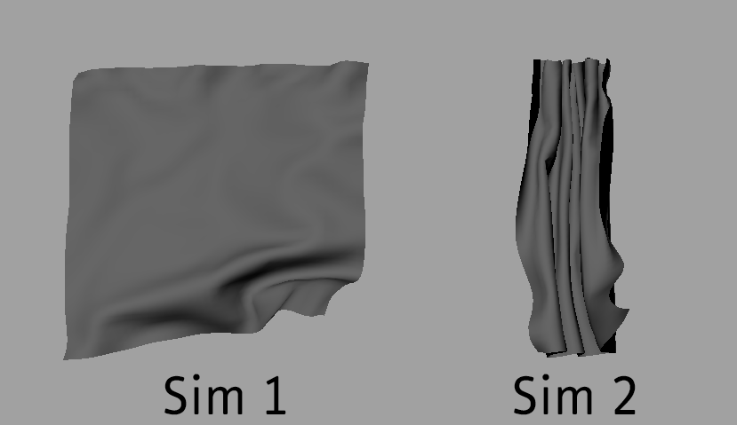
21. Now simulate this High Resolution cloth. Hopefully you will see that is follows the Alembic guide quite closely, but will also have some extra details. I have not changed any nCloth attributes apart from self-collision width. All the motion is made with the constraints.


Here is one I made earlier


High Resolution nCloth test from Daniel Sidi on Vimeo.

Monday 18 May 2015

Blending nCloth caches using Blendshapes


With many thanks to David Knight, nCloth guru, I present his method for blending two nCloth caches on a per vertex basis. You can have one half of a nCloth following one cache and the other half following a different cache.


1. Create two simulations for your cloth sim. Use a copy of the mesh for each sim. If the meshes do not match exactly (same number of vertices) then this method of blending will not work.

In my example I have one wide simulation and one which is narrow.


2. Cache your simulations.

3. Make another copy of the mesh, label it 'blendMesh'

4. Select the two nCloth meshes and finally shift-select blendMesh. Create a Blend Shape deformer (Create Deformers > Blend Shape)

5. In the Blend Shape attributes, set the weights for each input to 1.0


6. Assign weights per vertex. To do this open the Paint Blend Weights Tool (in the Edit Deformers menu). Do not manually paint blend weights because the sum of blend weights on each vertex must be equal to 1.0. Painting will not allow fine control. You can edit blend weights per vertex  manually in the Component Editor, but it is also possible to use an image set weights.

7. I have created some ramps in photoshop and saved them as TIF files. First I created the blengMap_H ramp, then I inverted the image (ctrl-I) which will subtract the value of each pixel from 1.0. That inverted image becomes blendMap_H_inverted. This will ensure that when the two ramps are added together the result will equal 1.0


I followed the same procedure to create the vertical ramps. The version of the ramp you need to use will depend on the orientation of your simulations. It's useful to have any combination of ramps saved in a library.

8. Apply the blendMap ramp to the Blend Shape deformer. Choose one of the Targets on the Blend Shape node and then under the Attribute Maps section, press Import and browse to where the blendMap ramps are stored.


Once the blendMap is assigned to the first target, chose the second target and assign the inverted blendMap to it.

That's it. You should now have a mesh which one end follows one cache and the other end follows a different cache.


Thursday 7 May 2015

nCloth Matching Mesh Constraint

If you want a high resolution nCloth, it can be very slow to simulate. One method is to generate a low resolution nCloth to produce the large scale movement that you require and then simulate a high resolution nCloth which follows the low resolution mesh on the large scale but will display small scale details of its own.

Here is one way to set up this systerm.

  1. Create a low resolution nCloth and simulate the large-scale motion. I will call that low resolution nCloth mesh "cloth_L0"
  2. Cache cloth_L0
  3. Smooth cloth_L0 using Mesh > Smooth. Be careful of having too many divisions as very high subdivision levels will cause significant slowing down of the simulation. I usually choose 1 to start with and then repeat the process if I need more detail.
  4. Export the smoothed cloth_L0 as Alembic using Pipeline Cache > Alembic Cache > Export Selected to Alembic. If you want to preserve UVs, remember to tick the check box in the options box.
  5. Import the Alembic file bac in to your scene. Rename that imported mesh as "Alembic_Import_L1"
  6. Duplicate Alembic_Import_L1. Rename the duplicate "cloth_L1"
  7. Create an nCloth from cloth_L1
  8. Select cloth_L1 and shift-select Alembic_Import_L1, then create an Attract to Matching Mesh constraint using nConstraint > Attract to Matching Mesh 
  9. In the constraint, choose a Dropoff Distance that makes sense in your scene. You want cloth_L1 to be able to deviate just enough from Alembic_Import_L1 to add some good detail, but not so much that it no longer the follows the large scale motion of the original simulation.
  10. In the Strength Dropoff ramp, create a profile that has a value of 0 in the left and 1 on the right. An exponential curve will work well.
  11. Tune the forces acting on cloth_L1 to give a variation over the movement of cloth_L0.
You should now have a high resolution nCloth which follows a low resolution cloth but has extra details. This process can be applied any number of times, depending on the power of your workstation.


In my example above I have chosen to use a division level of 2 because the original mesh was so low resolution I knew I would require quite a lot more resolution to get more detail.

Wednesday 6 May 2015

Velocity Field from Moving Geometry

If you want to create a velocity field from a moving mesh, here is a way to do it:


1. With your geometry selected, emit nParticles.


2. For the emitter, set:
  • Emitter Type to 'surface'
  • Increase the rate to, say, 50000 (depending on the size of your mesh)
  • Key the emission rate so that emission stops after a couple of frames.
  • Emission Speed and Normal Speed to 0
  • check the 'Need Parent UV' option


  4 Add the following per-particles attributes:
  • parentU
  • parentV
  • goalU
  • goalV


Make a creation expression on the nParticle object:

goalU=parentU;
goalV=parentV;


 6. Assign the geometry mesh as a goal for the nParticles. Set the Goal Smoothness to 0 and Goal Weight to 1.0


 Now you should have some particles sticking to the mesh.

7. Create a fluid container. You can use auto-resize if you want.

8. Select the fluid and the nParticles and create a fluid emitter.


 9. Set the emission to zero for Density, Heat and Fuel. Set the emission speed attributes to 'Add' and the Inherit Velocity to a value greater than zero.


That's it. You should now have the nParticles emitting velocity in the fluid. You can visualise the velocity field with the Velocity Draw option on the Fluid shape node.

You can use the velocities generated by this method to drive other simulations - nCloth, particles or fluids.


Wednesday 22 April 2015

Softimage button to apply a saved preset to a tool


Let's say you have a good preset for the Curve_To_Mesh tool and you want to apply that preset many times to different curves. It is slow to keep loading the preset manually each time you apply the tool.

Here is a way to apply the tool and then apply the preset in one handy button:

Firstly create the preset for the tool and save it somewhere. You will need the path to the preset later.


Next, open the script editor and copy the command form a previous usage. There are some command arguements that I am not yet familiar with, so copying from a previous usage guarantees that the syntax is correct.


for each curveObj in Selection
ApplyGenOp "CurveListToMesh", , curveObj, siUnspecified, siPersistentOperation, siKeepGenOpInputs
next


for each polyObj in Selection
LoadPreset "C:\Users\3d\Autodesk\Softimage_2012_Subscription_Advantage_Pack\Data\DSPresets\Operators\d1.Preset", (polyObj+".polymsh.CurveListToMesh")
next


Now I create a new Shelf


In the new shelf, I create a new Toolbar


Now I can drag my code from the script editor into the toolbar. That creates a button.


The first line reads the selection and runs the tool on the selected curve(s).

Softimage will have the newly created poly mesh object already selected, which makes the next part so much easier.

The second line gets the name of the selected poly object and applies the preset to the stack. This is where wou will need the location of the preset. Also, note the syntax of the last argument.

Having come from a Maya and MEL background I found this syntax really easy to pick up.

Monday 20 April 2015

Extending a camera track in PFTrack

If you have tracked a shot in PFTrack and then the shot gets extended and you want to extend your track, but keep the old solve, here is the workflow which worked for me.


  1. Import the extended clip
  2. Copy your node tree in PFTrack. I created a new Node Page using the P+ button.
  3. Paste your node tree into the new node page. I do this so that I don't accidentally overwrite the existing solve.
  4. If you have any User Tracks, select and export them.
  5. If you have any Auto Tracks, select and export them as well.
  6. Connect the new clip with the extra frames into the top of your tree.
  7. When you connect the new clip, the User Tracks and the Auto tracks will not work anymore. Select all the User Tracks and delete them. Then Import the tracks you exported in step 4
  8. Do the same with the Auto Tracks.
  9. Your User Tracks will now have keyframes only where they were previously tracked. You now need to track the un-tracked frames for all of those User Tracks. Select them and press the Track button in the direction you need to fill.
  10. The Auto Tracks will also need to be tracked for the missing frames. Simply select them all and press the Auto Track button. Select 'extend' when the dialogue box appears.
  11. You now have all the trackers in 2D, they need to be solved for 3D. Go to the Camera Solver node and press the Solve Trackers button.
  12. Now you are ready to extend the camera solve. In the Camera Solver node, press the extend button in the direction you need. The camera solve will extend out to the new frames and you should now have a camera for the whole shot which does not deviate from the old solve.